
Four-channel ESC boards in 45A, 80A and 110A configurations, with AM32 firmware, DShot300/DShot600/PWM inputs and 30.5 × 30.5 mm mounting.
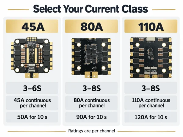
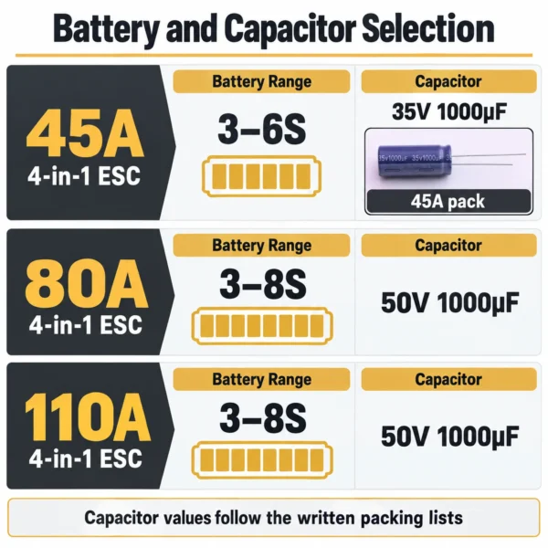
Battery range: 45A: 3–6S; 80A and 110A: 3–8S. Select by motor demand, cooling and the complete power connection.
| Configuration | Request a quote |
|---|---|
| 4IN1-ESC-45A 3–6S / 45A per channel |
|
| 4IN1-ESC-80A 3–8S / 80A per channel |
|
| 4IN1-ESC-110A 3–8S / 110A per channel |
Start with battery chemistry, cell count and fully charged voltage. Then match the listed current class to motor demand, propeller load, operating duration and installed cooling. The figures below are catalog specifications for the individual configurations.
| Parameter | 45A | 80A | 110A |
|---|---|---|---|
| Battery range | 3–6S | 3–8S | 3–8S |
| Listed input voltage | 10–26.4 V | 10–35.2 V | 10–35.2 V |
| Continuous current, per channel | 45 A | 80 A | 110 A |
| Burst current, per channel, for 10 seconds | 50 A | 90 A | 120 A |
| Catalog weight | 15.4 g | 29.6 g | 30.6 g |
| High-current PCB area | 6 layers, 2 oz copper | 8 layers, 2 oz copper | 8 layers, 2 oz copper |
Current ratings are per channel. They do not establish the combined continuous rating of the shared battery connector or power leads. Confirm suitability for your airflow, ambient temperature and duty cycle. Confirm the weight scope with the quotation.

All three configurations use AM32 firmware and list DShot300, DShot600 and PWM control inputs. The catalog specifies a dual-board PCB design, 24 power MOSFETs, a 32-bit 48 MHz controller, onboard current sensing and a TVS component.
Identify the exact hardware revision, firmware target and supplied release before planning an update. A matching current class or firmware platform alone does not identify a compatible firmware file. Include any controlled coating, substrate or component requirements in your inquiry.
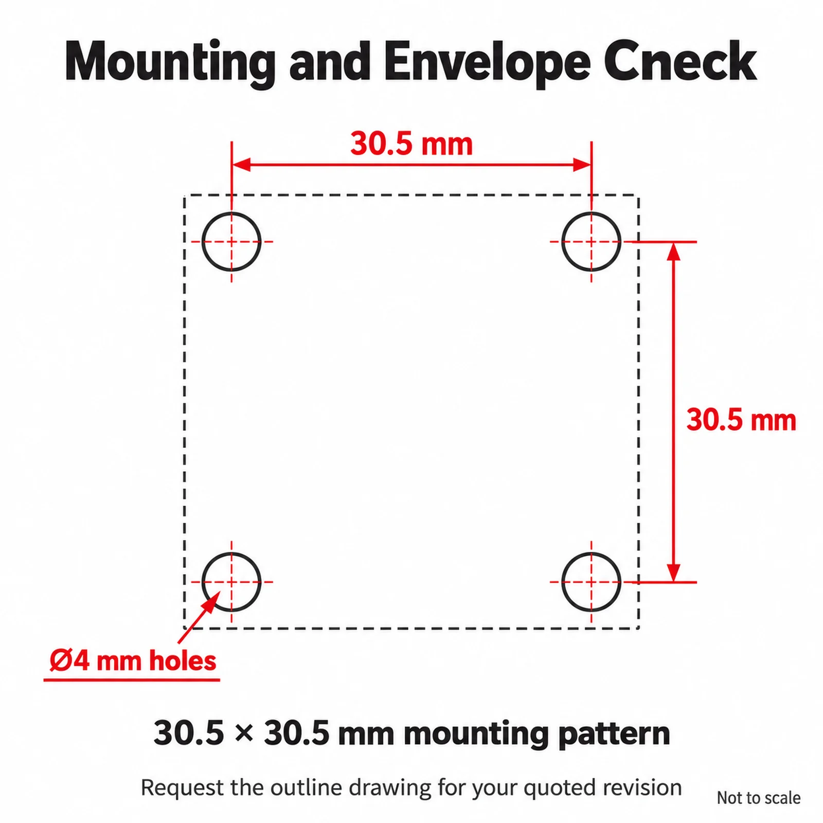
The listed mounting pattern is 30.5 × 30.5 mm with 4 mm mounting holes. This is the hole spacing, not the complete board size. Request the outline drawing for the quoted revision to check stack height, enclosure space and connector clearance.
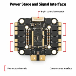
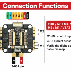
The signal interface uses an 8-pin SH-style connector with 1.0 mm pitch. Listed functions include M1–M4 motor-control inputs, VBAT, GND, CUR and NC. Each motor channel has three phase pads, while the board uses a shared battery input.
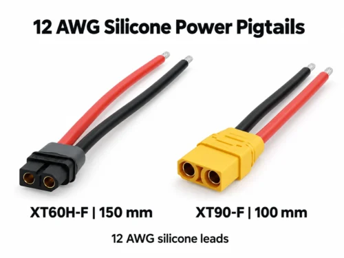
Check every pin function and connector orientation against your flight controller. Equal connector pitch does not guarantee compatibility. The 45A pack lists 12AWG power leads; specify gauge and length for an 80A or 110A order. Size the complete shared power path for your system demand.
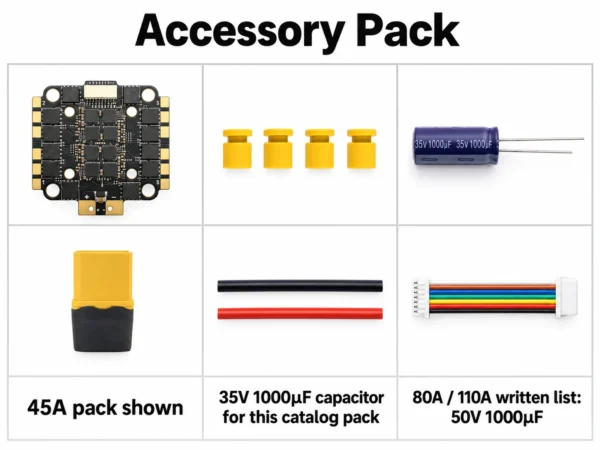
The reference packs below distinguish the capacitor and battery connection supplied with each current class. Confirm the complete accessory list and lead lengths in the quotation.
| Item | 45A configuration | 80A / 110A configurations |
|---|---|---|
| ESC board | 1 | 1 |
| M3 shock-absorbing grommets | 4 | 4 |
| Capacitor | 35 V 1000 µF × 1 | 50 V 1000 µF × 1 |
| Battery connection | XT60 connector × 1, plus 12AWG power leads | XT60 power lead × 1; confirm gauge and length |
| Signal cable | 8-pin SH-style 1.0 mm cable × 1 | 8-pin SH-style 1.0 mm cable × 1 |
For an 8S configuration, identify the 50 V capacitor explicitly in the order. Flight controller, motors and propellers are ordered separately.

Select the 45A, 80A or 110A configuration and list sample and batch quantities separately. Include your flight-controller reference and the electrical and installation requirements described above so the proposed board and accessories can be reviewed together.
| Item | Purchasing information |
|---|---|
| Quoted Configuration | Identify the board revision, firmware target and supplied release. Confirm the capacitor, power leads, signal cable and mounting accessories against the selected reference pack. |
| Samples & MOQ | Sample availability, charges and minimum order requirements are confirmed for the selected board, accessory list and quantity. |
| Custom Requests | Submit artwork for OEM labels or neutral presentation. Alternative leads, pin arrangements and packaging require an agreed bill of materials; hardware or firmware changes remain subject to feasibility review. |
| Documents & Repeat Orders | Identify any required specification, outline drawing, pin map, inspection record, traceability information or conformity document for confirmation. For repeat orders, retain your purchasing reference, board revision, firmware details, harness orientation and accessory list. |
| Item | Purchasing information |
|---|---|
| Preparation / Production Lead Time | Timing is confirmed for the agreed configuration, quantity and packing. Sample preparation and batch preparation or production estimates should be distinguished where applicable. The quotation should state the starting conditions, required approvals and estimated dispatch timing. |
| Shipping & Transit Time | Provide the destination country, postal code and required arrival date. Freight cost and estimated transit time are confirmed separately from preparation or production time. |
| Price & Payment Terms | Confirm the pricing unit, supplied contents and any separate customization, setup, packing or document charges. Payment and delivery terms are agreed in the quotation. |
| Inspection & After-Sales | Include any required checks, acceptance criteria or supporting records with your enquiry. Applicable warranty terms, defect-reporting procedures and replacement arrangements require confirmation before purchase. |
Start with battery voltage, motor demand and cooling. The 45A version lists 3–6S; the 80A and 110A versions list 3–8S. Check the complete propulsion setup and shared power connection before choosing a current class.
Confirm the exact target and supplied release for your board revision before making firmware changes. Do not select a file from the current rating alone.
Check mounting, input protocol, connector orientation and every pin function. Matching 30.5 mm spacing or a 1.0 mm connector pitch alone does not confirm compatibility.
The reference pack includes one board and the listed accessories for the selected configuration. Confirm capacitor voltage, power leads and signal cable with the quotation. The flight controller, motors and propellers are separate items.
No. The channel rating does not establish the continuous rating of the shared XT60 connector, leads or complete battery connection.
An IP rating and BEC output are not specified. Include enclosure and regulated-power requirements in your inquiry.
Send the model and board quantity, battery chemistry and fully charged voltage, motor model and KV, propeller, expected current and duty cycle, flight-controller model and pin diagram, and available installation space. Include required leads, capacitor, signal cable, labels, destination and target date.
Attach your electrical bill of materials or integration drawing.
Request an ESC Quote or review your selected models in the Inquiry List. For separate power-lead requirements, see our silicone power pigtails and specify the connector, gauge and length needed.
| Configuration | 4IN1-ESC-45A, 4IN1-ESC-80A, 4IN1-ESC-110A |
|---|

Use the exact model and revision when checking specifications and compatibility.

Confirm whether the offer covers individual parts, sets or complete assemblies.

Discuss availability, quantity, lead time and delivery terms for each inquiry.
Send your model, quantity and destination to discuss drone parts availability and supply terms.