
Understand what IMU, GNSS, compass, barometer, optical-flow and obstacle sensors contribute to flight control—and the environments that can defeat them.
Drone flight controller sensor limitations begin with a simple fact: the sensors do not create a perfect picture of the world. They measure different physical quantities, with different errors and environmental limits. The flight controller fuses those measurements into estimates of attitude, height, heading, velocity and position. Obstacle sensors add another partial view. Safe operation depends on knowing which estimate a function needs and what can make it unreliable.
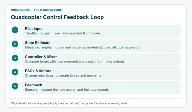
The quadcopter flight-control loop turns these estimates into motor commands. The sensors discussed here describe common system options; an individual FPV build may omit GNSS, a compass, a barometer or proximity sensors. Check the exact hardware and firmware before expecting position hold or obstacle response.
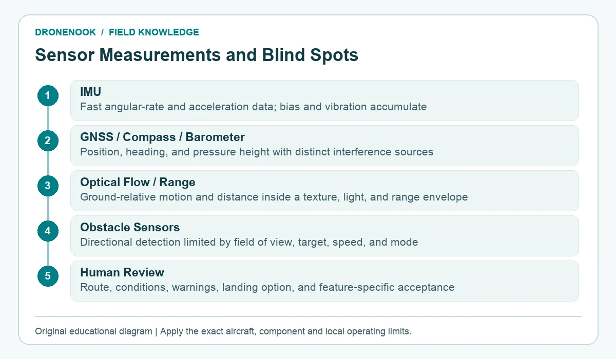
An inertial measurement unit normally includes gyroscopes and accelerometers. Gyroscopes measure angular rate; accelerometers measure specific force along their axes. These measurements arrive quickly and are essential for stabilisation, but they are not a complete position system. IMU drift in drone flight controllers can grow as small sensor biases are integrated over time; vibration can further corrupt the measurements.
The estimator combines inertial measurements with slower or absolute references. This is why it is more accurate to say the IMU contributes to attitude and motion estimates than to say a gyroscope directly “knows the horizon.” To investigate IMU drift in drone flight controllers, check installation orientation, vibration, required calibration and sensor health before assuming a software fault.
GNSS receivers use satellite signals to estimate position and velocity. They support functions such as location display, position modes, home-point recording and return features when the rest of the system is configured and healthy. Their limitations include blocked sky view, reflected signals near buildings, interference, jamming, poor satellite geometry and time needed to establish a valid solution.
A magnetometer senses the local magnetic field to help estimate heading. Motors, power wiring, steel, vehicles, reinforced concrete and other magnetic sources can disturb it. Repeated calibration does not remove a bad installation or a magnetically contaminated launch point. Follow the exact manufacturer’s calibration instruction and investigate the environment when heading changes unexpectedly.
Understanding barometric altitude vs terrain clearance starts with the reference: a barometer estimates altitude from air pressure. Propeller wash, enclosure pressure, weather changes and temperature can influence it. It is useful for vertical estimation, but its height reference and accuracy should not be confused with terrain clearance. A drone can hold a barometric altitude while the ground rises toward it.
Downward optical flow compares successive images to estimate motion relative to the visible surface. The main drone optical flow limitations indoors are insufficient texture, poor light and a surface outside the usable height range. Repeating patterns, shiny floors, darkness, moving water, vegetation moving in wind and a surface outside the sensor’s range can weaken or mislead the estimate.
Optical flow is often paired with a downward rangefinder because image motion alone does not provide the scale needed to convert pixels into ground-relative velocity. Rangefinders may use laser or infrared light, ultrasound or radar. Their minimum and maximum ranges, field of view, target reflectivity and surface angle matter. When a rangefinder supplies scale, drone optical flow limitations indoors depend on both the camera and the rangefinder. If the aircraft leaves that working envelope, source switching and the resulting behaviour are firmware- and configuration-specific.
“Obstacle avoidance” may describe stereo cameras, depth cameras, lidar, radar, one or more narrow rangefinders, or a fusion of sources. Sensor direction determines coverage. A forward sensor does not see sideways motion, and a nominal 360-degree sensor may still have exclusions caused by the frame or payload.
Common drone obstacle avoidance blind spots include:
An avoidance algorithm may stop, slide, reroute or trigger another response. Those behaviours are not equivalent. ArduPilot’s own documentation distinguishes strategies by vehicle, mode, object and sensor configuration. Document drone obstacle avoidance blind spots for the named system alongside its response strategy and the evidence from product documentation and controlled acceptance tests.
A state estimator can compare independent measurements and reduce reliance on an inconsistent source. It cannot guarantee a correct result when several sources share the same environmental problem, when a failed source still appears plausible, or when the required source is absent. A valid position-control mode needs more than an installed GNSS module: it needs a healthy position estimate, correct configuration and enough control authority for the conditions.
Use warnings and estimator status as information, not as an invitation to keep flying until the automation solves the problem. Unexpected drift, position jumps, heading disagreement, repeated mode rejection or unexplained avoidance behaviour justify a conservative response under the aircraft’s operating procedure.
| Required function | Measurements it depends on | Limiting environment to document | Unsupported condition |
|---|---|---|---|
| Self-level attitude | IMU and estimator | Expected vibration and temperature | Orientation or attitude disagreement |
| Position hold | Position, velocity, heading and height estimates | Open sky and intended operating area | Invalid or unstable estimate |
| Height planning | Pressure-derived height and, where fitted, ground-distance measurements | Barometric altitude vs terrain clearance over changing ground | Pressure-height hold mistaken for ground clearance |
| Low-altitude indoor hold | Optical flow, range and IMU | Actual floor texture and lighting | Surface outside working envelope |
| Obstacle response | Named proximity sensors and algorithm | Approach direction, speed and target types | Unverified coverage or braking margin |
Use each row to state which measurement makes a requested function possible, and which condition removes that support. Record the exact hardware, firmware, mode and documented sensor envelope; this is a dependency map, rather than an installation or channel-configuration checklist. Do not use a successful test against a large wall to claim detection of cables or branches. Do not test a blind spot by flying toward people, vehicles or valuable property.
The pilot or operating team still chooses the route, monitors conditions, preserves a safe landing option and avoids relying on an unverified feature. Geofencing does not grant airspace permission; return-to-home is not obstacle avoidance; a live camera does not provide a complete view around the aircraft. Current local rules and the aircraft documentation remain part of the operating decision.
The DroneNook guide to FPV ESC selection covers power-stage and flight-controller interfaces. This article stays at the sensor and state-estimation boundary: what measurements support control, and where those measurements can fail.
Turn drone flight controller sensor limitations into sourcing requirements: specify the required function, sensor models, flight-controller hardware, firmware and operating environment. Ask which conditions invalidate that function and what evidence supports the stated limits. The drone parts RFQ checklist helps organise the remaining compatibility and acceptance information.
Book basis: Patrick Sherman, Getting Started with Drones and Model Airplanes (Chapter 5, Bits and Pieces: What Is Inside?); Curt Simmons, Drone Piloting For Dummies (Chapters 2–4, First Flight, Control and Maintenance); Jason Goss, FPV Drone Handbook (Chapters 5, 15 and 19, Flight, Configuration and Maintenance). Exact component, aircraft, firmware and local operating requirements remain specific to the system and mission.
Supporting official references, rechecked 3 November 2026: