
See how total and differential thrust, state estimates and repeated feedback correction turn pilot inputs and disturbances into quadcopter motion.
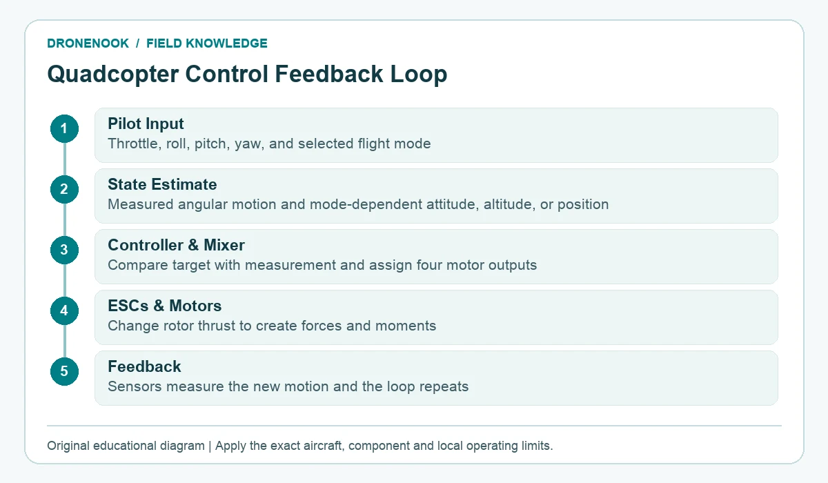
Understanding how quadcopter flight controls work begins with total thrust and the balance of thrust among four rotors. The flight controller measures how the aircraft is rotating, compares that motion with the pilot’s command, and continually changes motor outputs through the ESCs. The pilot asks for thrust or rotation; the controller performs the rapid corrections needed to produce it.
Each propeller accelerates air and produces a thrust force along its rotor axis. Add the four forces together and the result is the quadcopter’s total thrust vector. When the aircraft is level, that vector points mostly upward. In a steady hover, its upward component approximately balances the aircraft’s weight.
Drone throttle and total thrust control must be interpreted through the active mode. Increasing all four rotor thrusts together raises total thrust. Reducing them lowers it. The word “throttle” is convenient, but it does not always mean a direct motor percentage. Depending on the firmware and flight mode, the stick may command a thrust level, climb rate or another controlled quantity. The model-specific manual and mode definition determine the exact behaviour.
When a quadcopter tilts, its total thrust vector tilts too. Part of the thrust now acts horizontally, accelerating the aircraft across the ground. Less of the same total force remains vertical, so a controller or pilot that wants to preserve altitude must add enough total thrust to replace that lost vertical component. Attitude, altitude and position are therefore different states:
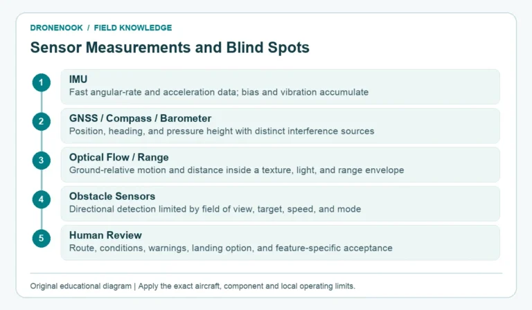
Understanding how quadcopter flight controls work requires separating self-level behaviour from navigation. A mode that returns the aircraft to level attitude does not necessarily hold altitude or position. Wind can push a level aircraft sideways unless the system also has a valid position estimate and a mode that corrects position.
To roll, the flight controller creates a thrust difference between the left and right sides. To pitch, it creates a difference between the front and rear. The exact motors that speed up or slow down depend on the frame layout, motor numbering, propeller direction and firmware mixer. That is why a generic diagram should never replace the current configuration diagram for a named build.
Suppose a quadcopter needs to pitch forward. The controller creates a moment that lowers the nose and raises the rear. Once the aircraft reaches the requested attitude, the required motor correction changes: the goal is now to hold that angle rather than continue rotating. If the pilot asks to level, the controller commands the opposite moment until the measured attitude returns to the target.
Two quadcopter propellers normally rotate one way and two rotate the other. In steady flight, their reaction torques are arranged to balance. To yaw, the controller changes the balance between the clockwise and counter-clockwise rotor groups. It can create a net turning moment while keeping combined lift close to the requested amount.
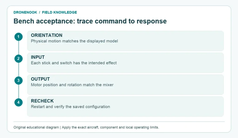
Propeller handedness, installed face, motor direction and the firmware’s expected layout must all agree. A motor-direction check is performed without propellers under the appropriate build procedure. Ordinary motor-direction setup is separate from a reversible-thrust or “3D” configuration; the latter requires compatible bidirectional hardware and different control logic.
To understand how quadcopter flight controls work, separate the mixer assigning outputs from each ESC driving its motor under the supported command protocol and configuration. Distinguishing a commanded output from the actual rotor response is central to quadcopter motor speed control basics. Battery condition, motor and propeller loading, and available output headroom limit how much correction can be produced. A control command cannot create thrust beyond the installed system’s capability.
The flight controller attitude feedback loop repeatedly checks the result of its commands. Its gyroscopes measure angular rates around the three axes. Accelerometers provide additional information used by attitude-estimation and self-level functions. The estimator and controller repeatedly compare the requested state with the measured state, calculate a correction, and update motor commands through the ESCs.
External disturbances appear as errors in that loop. A gust starts to roll the aircraft; the gyroscope detects the rotation; the controller changes motor outputs to oppose it. An uneven payload may require a persistent difference in motor output to hold level. The controller can compensate within its authority, but compensation does not make a poor centre of gravity, loose payload or overloaded motor system acceptable.
This article explains the loop without providing PID values. Gain settings depend on the aircraft, firmware, filters, propellers, structure and test method. Copying a number from an unrelated build can create oscillation or weak control. Use the aircraft or firmware’s supported setup and validation process.
| Control layer | Typical centred-stick result | What it does not prove |
|---|---|---|
| Rate/Acro attitude-rate control | Stops requesting roll or pitch rate; current attitude can remain | Level, altitude or position hold |
| Self-level/Angle control | Commands a level roll and pitch attitude | Horizontal position hold or fixed altitude |
| Altitude control | Commands a defined vertical behaviour | Resistance to horizontal drift |
| Position control | Can brake and hold a location when state estimates are valid | Obstacle avoidance or guaranteed accuracy |
Mode names and requirements vary. Current Betaflight documentation, for example, distinguishes Rate, Angle, Altitude Hold and Position Hold, while PX4 documents separate Stabilized, Altitude and Position modes. Similar labels across firmware families do not guarantee identical behaviour.
Imagine a level quadcopter holding a commanded attitude when a gust starts to lift its left side. The aircraft begins rolling right. The gyroscope reports angular rate; the estimator and controller use the measured state to calculate a correcting roll moment against the requested state. The exact filtering and control path depend on the installed firmware.
The mixer turns that correction into changes for the four motor outputs. For this conceptual Quad-X response, the mixer can increase thrust on the right side and/or reduce it on the left to generate the opposing roll moment, while keeping total thrust as close as available motor authority allows. The exact motor assignments still come from the installed mixer, not from this conceptual example.
The ESCs update the motors, the rotor thrust changes, and the unwanted roll rate falls. The gyroscope measures the new motion and the loop runs again. Once the measured state reaches the target, the temporary correction reduces; it does not keep accelerating the aircraft in the opposite direction. This repeated measurement and correction is the flight controller attitude feedback loop.
Understanding how quadcopter flight controls work helps separate the requested command, measured response and available thrust when interpreting symptoms. A slow response can come from limited control authority or conservative control settings; a persistent output difference can reflect an offset load or disturbance; oscillation means the measured response is repeatedly overshooting the target. Diagnosing a named aircraft still requires its logs and supported procedures. The published FPV ESC selection guide covers the ESC as an electrical and interface component; this article explains why that execution layer receives continuously changing commands. For sourcing references, compare DIY-959 and the caged training series. This control explanation does not establish a supplied curriculum, SDK or programming interface.
Book basis: Jason Goss, FPV Drone Handbook (Chapter 5, How a Drone Flies; Chapters 6 and 15, Stack and Betaflight); Patrick Sherman, Getting Started with Drones and Model Airplanes (Chapter 4, Aerodynamics; Chapter 5, Inside; Chapter 8, Controls); Sarah E. Kreps and James Patton Rogers, Drones: What Everyone Needs to Know (Chapter 1, Defining Drones). Exact component, aircraft, firmware and local operating requirements remain specific to the system and mission.
Supporting official references, checked 1 November 2026: